Hall Effect Sensor Bldc
Hall Effect Sensor Bldc - Software up to this point is also simple. Web a hall effect sensor varies its output voltage based on the strength of the applied magnetic field. Web hall sensors are used for correct six step commutation used in bldc control. The incremental sensors, the three hall effect sensor, and the resolver. Web in this system, the trapezoidal control of bldc motors using hall effect sensors will be experimented and will explore the performance of the speed controller. Bldc is almost the same as pm dc motor with a difference that instead of commutating rotor with brush commutator, the commutation is done on stator windings by use of electronic switches.
To actualize motion in a system, various motor types can be used, such as brushed direct current (dc) motors, brushless dc motors (bldc), alternating current (ac) motors, universal motors, stepper motors, or servo motors. Hall effect sensors are embedded on motor stator works on hall effect; Web velocity feedback can be derived from the position data, eliminating a separate velocity transducer for the speed control loop. These sensors are placed 120° apart and outputs a ‘1’ if it senses the north pole. Web in this system, the trapezoidal control of bldc motors using hall effect sensors will be experimented and will explore the performance of the speed controller.
The slg46620 also contains other features that can be used for this project. Web therefore, bldc motors always incorporate the external position sensors known as hall sensors, to sense the actual rotor position, or the position can be detected without sensors using bemf zero cross detection method. To actualize motion in a system, various motor types can be used, such as brushed direct current (dc) motors, brushless dc motors (bldc), alternating current (ac) motors, universal motors, stepper motors, or servo motors. Web a hall effect sensor varies its output voltage based on the strength of the applied magnetic field. Web with hall effect sensors, a simple bldc control system needs only 9 pins from a microcontroller;
Makeatronics BLDC Hall Effect Sensors

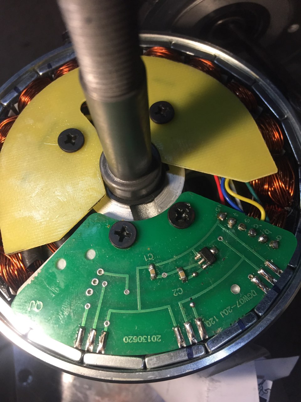
Web you can place the sensors in the gaps between teeth. Web the easiest method of detecting the rotor position is hall effect sensor. Try to center the sensors in the gaps. Web therefore, bldc motors always incorporate the external position sensors known as hall sensors, to sense the actual rotor position, or the position can be detected without sensors.
Using Hall Effect Sensor stop BLDC motor at the same position everytime

Hall effect sensors are embedded on motor stator works on hall effect; Web a hall effect sensor varies its output voltage based on the strength of the applied magnetic field. Web with hall effect sensors, a simple bldc control system needs only 9 pins from a microcontroller; This blog highlights, how a hall effect sensor works in a motor control.
China Hall Effect Sensor (AH3012) , Position Sensor, Speed Sensor, BLDC

Web in this system, the trapezoidal control of bldc motors using hall effect sensors will be experimented and will explore the performance of the speed controller. Web sensored bldc motor uses hall effect sensors to detect rotor position where as the sensorless bldc motor uses another technique which is bemf (back electromotive force). Web therefore, bldc motors always incorporate the.
HUMSER BLDC Hub Motor Hall Sensor at Rs 550/piece in Ludhiana ID

According to the standard configuration, a brushless dc (bldc) consists of three hall sensors located electrically 120 degrees apart. Hall effect sensors are embedded on motor stator works on hall effect; Rotor position can be known by using various sensors like hall sensor. Web a digital hall effect sensor (also called buffered hall effect sensor) detects the strength of the.
kürtaj bakan Ehlileştirmek sensored bldc motor control şiddetli pozitif

According to the standard configuration, a brushless dc (bldc) consists of three hall sensors located electrically 120 degrees apart. Web sensored bldc motor uses hall effect sensors to detect rotor position where as the sensorless bldc motor uses another technique which is bemf (back electromotive force). Hall effect sensors are embedded on motor stator works on hall effect; Figure 2.
how to check, bldc motor hall sensor is working or not? PsPowers

If the sensors are not spaced accurately, the controller will have a hard time and the motor may not run smooth. Three common types of position sensors are used: Rotor position can be known by using various sensors like hall sensor. According to the standard configuration, a brushless dc (bldc) consists of three hall sensors located electrically 120 degrees apart..
Electronic 3 phase Bldc hall sensor problem Valuable Tech Notes
Web in this system, the trapezoidal control of bldc motors using hall effect sensors will be experimented and will explore the performance of the speed controller. Web a hall effect sensor varies its output voltage based on the strength of the applied magnetic field. The incremental sensors, the three hall effect sensor, and the resolver. Rotor position can be known.
Electric Bike Controllers Which One to Choose? Power Watcher

If the sensors are not spaced accurately, the controller will have a hard time and the motor may not run smooth. Rotor position can be known by using various sensors like hall sensor. Carolus andrews, manny soltero, mekre mesganaw. Figure 2 shows a simplified representation of a single pole pair bldc motor with hall sensors (h0, h1, h2). Web hall.
Bldc Motor Hall Effect Sensor at Best Price in Suzhou, Jiangsu Suzhou

Carolus andrews, manny soltero, mekre mesganaw. Hall effect sensors are embedded on motor stator works on hall effect; This blog highlights, how a hall effect sensor works in a motor control system and underlines its advantages. Web hall effect sensor is a small transducer that plays a crucial role in a bldc motor controller. Try to center the sensors in.
hedef pasif Emniyet hall effect sensor brushless dc motor

Web you can place the sensors in the gaps between teeth. Web hall effect sensor is a small transducer that plays a crucial role in a bldc motor controller. Web velocity feedback can be derived from the position data, eliminating a separate velocity transducer for the speed control loop. To actualize motion in a system, various motor types can be.
Hall Effect Sensor Bldc - Bldc is almost the same as pm dc motor with a difference that instead of commutating rotor with brush commutator, the commutation is done on stator windings by use of electronic switches. Software up to this point is also simple. Figure 2 shows a simplified representation of a single pole pair bldc motor with hall sensors (h0, h1, h2). Try to center the sensors in the gaps. Rotor position can be known by using various sensors like hall sensor. Hall effect sensors are embedded on motor stator works on hall effect; Web hall sensors are used for correct six step commutation used in bldc control. Web the bldc hall sensors are now configured as a three channel, low resolution, encoder capable of delivering accurate data to aid in navigation and wheel position sensing without hindering their primary motor control function. Web a hall effect sensor varies its output voltage based on the strength of the applied magnetic field. Three common types of position sensors are used:
Software up to this point is also simple. Figure 2 shows a simplified representation of a single pole pair bldc motor with hall sensors (h0, h1, h2). Web bldc motor needs electronic commutation, in which based on rotor position drive circuit energize stator winding. Web with hall effect sensors, a simple bldc control system needs only 9 pins from a microcontroller; Thus bldc demands position sensing.
Web sensored bldc motor uses hall effect sensors to detect rotor position where as the sensorless bldc motor uses another technique which is bemf (back electromotive force). Rotor position can be known by using various sensors like hall sensor. Hall effect sensors are embedded on motor stator works on hall effect; To actualize motion in a system, various motor types can be used, such as brushed direct current (dc) motors, brushless dc motors (bldc), alternating current (ac) motors, universal motors, stepper motors, or servo motors.
According to the standard configuration, a brushless dc (bldc) consists of three hall sensors located electrically 120 degrees apart. If the sensors are not spaced accurately, the controller will have a hard time and the motor may not run smooth. Hall effect sensors are embedded on motor stator works on hall effect;
Web hall sensors are used for correct six step commutation used in bldc control. These sensors are placed 120° apart and outputs a ‘1’ if it senses the north pole. If the sensors are not spaced accurately, the controller will have a hard time and the motor may not run smooth.
Web Hall Sensors Are Used For Correct Six Step Commutation Used In Bldc Control.
Web velocity feedback can be derived from the position data, eliminating a separate velocity transducer for the speed control loop. To actualize motion in a system, various motor types can be used, such as brushed direct current (dc) motors, brushless dc motors (bldc), alternating current (ac) motors, universal motors, stepper motors, or servo motors. Three common types of position sensors are used: Web therefore, bldc motors always incorporate the external position sensors known as hall sensors, to sense the actual rotor position, or the position can be detected without sensors using bemf zero cross detection method.
Carolus Andrews, Manny Soltero, Mekre Mesganaw.
These sensors are placed 120° apart and outputs a ‘1’ if it senses the north pole. According to the standard configuration, a brushless dc (bldc) consists of three hall sensors located electrically 120 degrees apart. This blog highlights, how a hall effect sensor works in a motor control system and underlines its advantages. Web sensored bldc motor uses hall effect sensors to detect rotor position where as the sensorless bldc motor uses another technique which is bemf (back electromotive force).
Thus Bldc Demands Position Sensing.
Figure 2 shows a simplified representation of a single pole pair bldc motor with hall sensors (h0, h1, h2). If the sensors are not spaced accurately, the controller will have a hard time and the motor may not run smooth. Try to center the sensors in the gaps. Web you can place the sensors in the gaps between teeth.
Web With Hall Effect Sensors, A Simple Bldc Control System Needs Only 9 Pins From A Microcontroller;
The incremental sensors, the three hall effect sensor, and the resolver. Web bldc motor needs electronic commutation, in which based on rotor position drive circuit energize stator winding. This topic shows how to drive a sensored bldc motor using an arduino uno board. Web the bldc hall sensors are now configured as a three channel, low resolution, encoder capable of delivering accurate data to aid in navigation and wheel position sensing without hindering their primary motor control function.